Wednesday, March 30, 2011

GPS Logger + uBlox5 GPS


My parts finally arrived. I ordered a GPS logger from Adafruit and a uBlox5 GPS from DIY drones. Ublox has a program uCenter used to configure the uBlox5 GPS. The uCenter user guide is here. The GPS comes with an adapter so that it is compatible with the EM-406 type cable. So it works with the data logger which was designed for the EM-406.

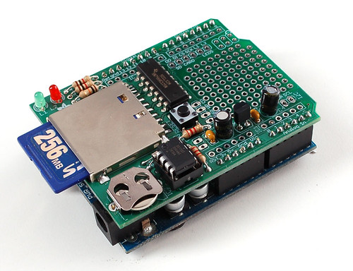
Tonight I soldered the components on the data logger board and fired it up with a FTDI cable. The uBlox5 ran at 9600bps. You can get it setup in several different ways from DIY drones and I chose standard NMEA, because the code from Adafruit parses NMEA sentences.

The Arduino serial monitor started spitting our NMEA without a hitch. I was kind of surprised that it just worked.

I chose the uBlox because its very highly regarded by the people over at diydrones and it has a refresh of 4hz, and resolution with WAAS of 2 meters.

Saturday, March 26, 2011

I2C sensors - Compass

I've already posted about the compass that I'll be using in the boat. But as with anything there is more to it that just the specific part. In fact we have several options when it comes to tilt compensation compasses.
  • LSM303, $30, I2C, no internal calculations, accuracy depends...
  • HMC6343, $150, I2C, tilt compensation calculated internally, accuracy of 2 degrees
  • OS5000-s, $260, RS232, tilt compensation calculated internally, accuracy of 0.5 degrees
As I said earlier I'll probably go with the HMC6343. So lets talk about I2C and the Arduino. Most of this information was taken from tronixstuff. Another great tutorial is at Robot Electronics.
  • I2C uses pins A4 for SDA (data) and A5 for SCL (clock)
  • I2C needs Arduino librarywire.h>
  • The default (factory) HMC6343 7-bit slave address is 0x32 for write operations, or 0x33 for read operations.
  • The compass requres pull-up resisters on SDA and SCL to 3.3v and supply voltage of 3.3v
  • The Arduino has built in pull-up resisters on A4, A5, but it is to 5v...
To get the correct logic and supply voltage to the HMC6343 it looks like you can use a logic level converter at least at $1.95 they don't cost much...

I initially thought that I could use 3 wires for each of my sensors and use servo connectors. Now I'm starting to realize that most of the sensors take more connections that that. I2C components require 4 wires.

More Resources on Arduino I2C and Level Shifting

Tuesday, March 22, 2011

Paddlewheel Speed Sensor + Wind Vane Question

Here is the paddlewheel. Its a vacuform plastic housing with an acylic paddlewheel. The rod is the same carbon fiber that I used for the anemometer. I already have all the sensors working with the arduino so now all I have to do is put the pieces together.

The question I've been wrestling with is: How do you average reading from the wind vane? Say you have 5 readings at varying degrees (from 0-360). For example; 10, 5, o, 355, 340. A simple average will be wrong because the readings wrap around a circle... Glen addressed this, but there are special cases that don't work in his solution. For instance when you have a reading like: 5,5,5,270,270.

Resources:

Sunday, March 20, 2011

Anemometer Nearly Done

This is the most high-tech pinwheel I've ever made. Sealed ball bearing (with flange), Aluminum tube, Carbon fiber rod, heat molded .02" plastic cups, and cast transparent (ortho) acrylic. The cups are probably a little small at about 1in diameter. I'd like the anemometer to be sensitive to 1 knot (or less if possible) because these little boats don't sail in heavy winds. But testing larger cups later would be very easy.

I finally got the photo reflective sensor working as well. It needed a 10k resistor. My problem was that I fried the first one. I guess I hooked something up wrong... Anyway at $2 each, not a biggie. But I only ordered 3 from china, so I don't want to have to wait 3 weeks for shipping again.

All my sensors have been tested WORKING! with the Arduino. Now its assembly time. Then calibration... Then putting the code for each sensor into one sketch with attachinterrupt() for the photo interrupters and damping for the wind vane.

Saturday, March 19, 2011

Finally got the photo interrupter working!

A photo of my working photo interrupter. Here is the trick to getting a new photo interrupter working (tipped off by this thread). There are 2 sides to the gate; the transistor and the emitter.

Phototransistor:
  • look at the datasheet and see which side is the emitter and which is the collector.
  • start by setting up the phototransistor as an analog input analogread() will output values from 0-1023
IR emitter:
  • look at the datasheet to see how much voltage and current the LED can handle. Mine was 50mA
  • Hook up the LED to that output. In my case digital I/O gives 5V and 40mA.
Test:
  • watch the serial monitor I started off getting values that ranged from 0 to 3, then after fiddling with resistors (taking away the resistor to the emitter and adding a 10K to the transistor).
  • Got to the point where I read 10-20 when the gate was blocked and 1010-1020 when the gate is open. (my Photo interrupter took a 10K resistor, my Photo Reflective Sensor will take a 100k or 1m resistor all I have is 10K resistors and 5 of them in series brought the reading up to 400)
  • Now change the code from analogRead() to digitalRead() (and switch the input wire) see if you get 111100001110001111 when you move something between the gate.
Resources:
Here is the test code that I used:

int val;

void setup()

{

pinMode(13, OUTPUT);
pinMode(2, INPUT);

Serial.begin(9600); // sets the serial port to 9600

digitalWrite(13, HIGH);
}

void loop()

{

val = digitalRead(2); // read digital input pin 2
//val = analogRead(0); // read analog input pin 0

Serial.print(val); // prints the value read
Serial.print(" "); // prints a space between the numbers

delay(100); // wait 10ms for next reading

}

Friday, March 18, 2011

SiRFIII GPS Logger Shield


The output from the EM-406a is in NMEA sentences. Each sentence starts with a '$'. There are a bunch of sentences that it can spit out, but only a few that we are interested in. For example sentences look at the EM-406a Manual.

Interesting sentences:
  • RMC-Recommended Minimum Specific GNSS Data, message 103,04
  • - this has all the basic data that you'd want for a boat; lat, long, speed (in knots)
  • VTG-Course Over Ground and Ground Speed, message 103,05
  • - this will give us the heading relative to magnetic north. That way we can directly compare the reading from the compass
Adalady has written code to test the GPS Sheild. There is also code for recording the GPS data and up to 3 analog inputs.

Telemetry Using Xbee Modules

For telemetry the Xbee appears to be the option. Adalady has a great tutorial on wiring up the arduino with an XBee for point-to-point communication using a $10 board available from Adafruit.com

DIYdrones.com also has board for connecting the XBee and some documentation. However, for a newbee like me it was a little sparse.

On the computer side of things all you appear to need is an FTDI cable (for either system).

Wiring the XBee to the arduino AND being able to reset the arduino remotely can be found here.

For communication over XBee the Arduino appears to need the NewSoftSerial library.

Compass With Tilt Compensation

After I get the GPS logger shield working the next objective is the compass. With the HMC6343, I'll get heading and pitch (or heel angle in a sail boat). From reading a little bit around the internet, it seems that this compass works very well, but you really have to watch out for motors and magnets. The interference screws up the heading results.


Compass communicates using the Wire Library

Code to test Compass attached to arduino
this is from a chinese robotics site, but the code is still the same.

Code Robbie Edwards in their sailboat:
// I2C related constants and variables
// Library includes

#include
#define HMC6343Address 0x32
// Shift the device's documented slave address (0x32) 1 bit right
// This compensates for how the TWI library only wants the
// 7 most significant bits (with the high bit padded with 0)
int slaveAddress = HMC6343Address >> 1; // This results in the 7 bit address to pass to TWI
// Compass measurement related constants and variables
byte headingData[6];


void init_compass(void)
{
Wire.begin(); // Open I2C to HMC6343
}

void getCompassData(void)
{
int i;
Wire.beginTransmission(slaveAddress);
Wire.send(0x50); // Send a "Get Data" (0x50) command to the HMC6343
Wire.endTransmission();

delay(2); // The HMC6343 needs at least a 1ms (microsecond) delay
// after this command. Using 2ms just makes it safe

// Read the 6 heading bytes, MSB first
// The resulting 3 16bit words are the compass heading, the tilt and roll in 10th's of a degree
// For example: a heading of 1345 would be 134.5 degrees

Wire.requestFrom(slaveAddress, 6); // Request the 6 bytes of data (MSB comes first)
i = 0;
while(Wire.available() && i < headingvalue =" headingData[0]*256" tiltvalue =" headingData[2]*256" rollvalue =" headingData[4]*256" vbthetac="headingValue/10;">

Saturday, March 12, 2011

Sailing the Soling with a GPS onboard


View Soling in a larger map

You have to really zoom in to see the route. I downloaded the data from my GPS in GPX format which included position, speed, and time.
  • Top Speed: 3.5 knots
  • Average Speed: 1 knot (included pre and post race)
GPX data can be convert to text with an online utility GPSVisualizer.

Photogate RPM sensor


My next problem to solve is the implementation of a photogate as a paddlewheel boat speed sensor and a second photogate to count RPM on the anemometer. I found this great little project in instructables.com that uses the attachInterrupt() arduino function. I'll use the same thing.

Sunday, March 6, 2011

Current Plan of Attack


Arduino + GPS Data Logger


V0.1 - (done)

  • GPS -measures at 1Hz to within 5m
    • Position
    • Vg - ground velocity
    • time stamp

V1.0

logs:

  • Arduino
    • Vs - boat speed
    • Va - apparent wind velocity
    • Ba - Apparent wind angle (without correction)
    • time stamp
  • GPS
    • Position
    • Vg - ground velocity
    • time stamp

V2.0

Logs:

  • Arduino
    • Vs - boat speed
    • Va - apparent wind velocity
    • Ba - Apparent wind angle (without correction)
    • Ta - Apparent wind angle wi
    • Phi - Heel angle
    • C - course of the boat
  • GPS
    • Position
    • Vg - ground velocity
    • time stamp

V3.0

sends data to a computer via xBees

  • Arduino
    • Vs - boat speed
    • Va - apparent wind velocity
    • Ba - Apparent wind angle (without correction)
    • Ta - Apparent wind angle wi
    • Phi - Heel angle
    • C - course of the boat
  • GPS
    • Position
    • Vg - ground velocity
    • time stamp
The GPS is a bluetooth Data Logger BT-335. The control program for MAC is available here. I'll get the sensors working and calibrated and a code worked out on the Arduino with a data logger first. Then start adding things.
I have been asked why I don't just use a GPS directly plugged into the Arduino. This definately would be a better solution to use the GPS logger shield. But because I'd like to keep it VERY simple at first and I'm on a small budget, I've chosen this path.

Apparent Wind Parameters


Here is a very good tracing to follow for understanding the basic angles involved in tacking up wind.

It's taken from a paper available here.

Data Logging

To break this project into manageable steps I've decided to make a first (in the boat) goal to record telemetry from the boat:
  • apparent wind angle
  • apparent wind speed
  • boat speed
  • GPS coordinates
It will be important to be able to consistently record these values to calibrate the sensors.

To that end I ordered a data logger shield to use with my Arduino UNO. With it I can record all the sensors on the boat. I have a bluetooth SiRF III data logger lying around somewhere that I'll also put in the boat. Both the shield and GPS time stamp and output to CVS so I should be able to get reasonable accurate telemetry.

I'll also need to find a wind vane / anemometer with trusted data output to compare to mine.

Friday, March 4, 2011

Velocity Made Good Calculation


Velocity made good (Vmg) from wikipedia is the velocity toward a mark. To compute Vmg the following quantities must be know:
  • Yacht speed -- Vs
  • Apparent wind direction -- (B - lambda)
  • Apparent wind speed -- Va
  • Leeway Angle -- lambda
"The solution of this equation electrically would require equipment both too costly and bulky forgeneral use. The further complication of correcting the measured values of Va and (B - lambda) to allowfor the errors introduced by the heeling of the yacht make an exact-solution computer impracticable." from R. N. B. Gatehouse

"Vmg is given by Vs cos gamma. The angle between the yacht's track and her fore-and-aft axis is the leeway angle lambda"


I think that the tiny 1/2 looking like sym

bol exponent position under the devision sign is 1/lambda.

By trig we have:


Electronic Instruments and Computers for Sailing Yachts


by R. N. B. Gatehouse


I've found that reading really old research is often more interesting than the cutting edge stuff. To see how ideas develop and in just a few minutes cover decades of development is really the essence of the information age. Here is just such a paper. Gatehouse suggest measuring true position by sighting known markers to triangulate your position which was considered unfeasible . Well a GPS is a whole lot easier, but wasn't around 1970.


Gleaned Points of Importance to ArduSkipper:

  • where to put the speedometer - "the boundary layer beneath the hull of a typical racing yacht was nowhere more than 1 in. thick and was only about 1/2 in. thick at a position 5 ft. aft of the forefoot, the position finally chosen for the sensor [on a 24ft boat]."

  • "The leeway angle, which is the angle between the yacht's fore-and-aft axis and the direction of motion through the water, reaches a maximum value when the yacht is close-hauled, this value varying between about 2° and about io°"

  • Wind Vane Error - the error of measurement of wind direction due to sail deviation seldom exceeds 3 degrees and is independent of wind velocity.,, [other researchers], indicated that the error was about + 7 degrees.... [Moreover] The error is such as to make the apparent wind angle greater than it really is.
  • Anemometer - The diameter of each cup is 1 in. and the length of its supporting arm is 1 1/2 in. Departures from linearity did not exceed 0.5 per cent within the speed range 2-60 knots.

Commenting Code


I have 5 major pieces of code that I'm trying to wrap my mind around.
right now I'm reading through everything and make TONS of comments. My programing skills are old minimal and rusty. I think I took 2 or 3 programing classes in college... As soon as I get a chunk commented I'll post it.

Wednesday, March 2, 2011

Apparent Wind angle correction for heel angle


Taken from here.

The Servos Arrived


Ordered the servos about 3 days ago from Servocity.com. I was surprised at how small and expensive they were. They were on sale (25%). Notice the 180 degree option on the first one. That is so the servo has enough travel to fully take in and let out the sheets.

Qty Description Unit Amount
--------------------------------------------------------------------------------
1 (37950S10) HS-7950TH Servo $149.99 $149.99
* Quantity Modifier $-37.50 $-37.50
* Option: Rotation is 180° (5445) $10.00 $10.00

1 (31085S00) HS-85BB Servo $19.99 $19.99
* Quantity Modifier $-5.00 $-5.00

Tuesday, March 1, 2011

Spruce for the Mast


Call around and Emerald Marine said they had some spruce that would work for my sailboat mast. I'd use aluminum, but its against the AMYA rules for a Soling one-design. I'd like to keep my boat legit.